RADIOS AND MICROWAVE ANTENNAS DEPLOYMENT
INTRODUCTION TO MICROWAVE ANTENNA AND TYPES
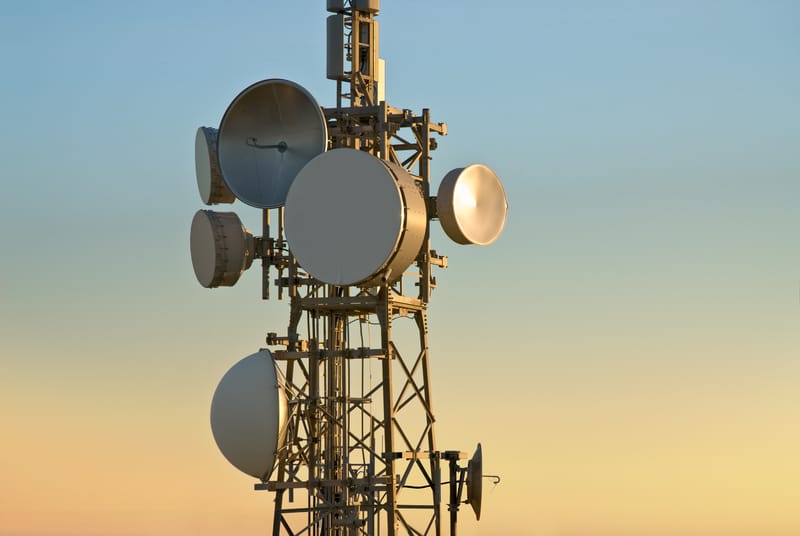
Before any device is called a communication device, it must be able to transfer data between equipment and persons. A microwave antenna is defined as a communication device for physical transmission and is used for broadcasting microwave transmissions between two or more places. They are very important elements for any microwave network-enabled system. Most types of microwave antennas are designed specifically to meet various mechanical and electrical requirements. Below are the key types of microwave antennas and their uses.
1. Micro Strip Patch Antenna: The microstrip patch antenna has a patch used for radiating that connects to a ground plane on one of its parts and a dielectric substrate on the opposite side. The patch antenna contains conducting metals such as gold and copper and has an operational frequency ranging between 100MHz and 100GHz. The patch antennas are popular due to their extent of usage and good performance. Microstrip antennas may replace conventional antennas as technology continues to evolve. Their application areas include paging devices, personal communication systems, cellular phones, and global positioning satellites.
2. Horn Antenna or Microwave Horn: This type of Microwave Antenna comprises a waveguide, which has flared end walls on the outside forming a structure that looks like a megaphone. The horns are used widely as antennas microwave frequencies above 300 MHz and ultra-high frequencies. They are used as directive and calibrating antennas for equipment such as microwave-radio meters, and automatic door openers.

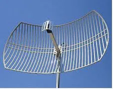
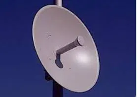
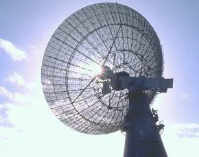
3. Parabolic Antenna: This is a parabolic-shaped and curved area that is used to direct the radio waves. The antenna is shaped like a dish thus it is referred to as a parabolic dish or dish antenna. One of the benefits of a parabolic antenna is that it has high directivity. Parabolic antennas are applied as radio telescopes and for point-to-point communication since they have high-end gain. Also, these antennas are used as radars. They require the transmission of a narrow beam wave of radio to some equipment such as airplanes and ships.
4. Plasma Antenna: This is a kind of radio antenna that uses plasma rather than metal elements as a development device. Metal elements have been used in antennas in the past years. Plasma antenna uses ionized gas for conduction. The gas is ionized when reception or transmission occurs. The plasma antenna can operate up to 90GHz frequency range. Thus, they can be applied in the reception and transmission of signals from radios. Besides, the antenna has a cutoff of high frequency. It’s able to receive and transmit signals of low and high frequency and it does not interact with the signals of high frequency. Some of the areas where plasma antennas are applied include 4G and radar systems, RFID, electronic intelligence, and high-speed digital communications.
5. MIMO Antenna: Multiple Inputs and Multiple Outputs (MIMO) antennas are applied in radio. They are used at the receiving and transmitting points to enhance the process of communication. MIMO antenna is among the best technologies in smart antenna. There are two ways of exploiting multiple antennas in MIMO. One, they are used in creating highly effective antenna directivity. They are also used in the transmission of parallel data streams. This is to add to the system’s capacity. Applications of MIMO antennae include RFID systems and mesh networks.
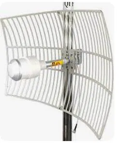
6. Omni Directional Antenna: These antennas receive and radiate energy in all horizontal directions equally. Omnidirectional antennas offer a perfect solution for applications that need good all-around coverage. In special applications, the antennas can be used to accommodate a specific down tilt to achieve near-field coverage.
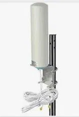
7. Tracking Antenna: These designs are made specifically to stabilize and align the antenna automatically. At the same time, they maintain the point-to-point path in the movement of a platform in unstable surroundings. Tracking antenna is routinely used in aviation, offshore drilling, marine, and mobile platforms. Here, the operators depend on Line-of-Sight (LoS) communications.
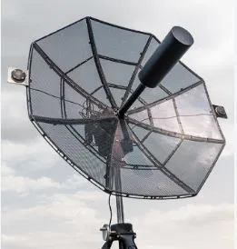
8. Yagi Antenna: This is a versatile antenna that utilizes a driven element. Behind the driven element is a reflector while in front of it is a director or several directors. The design of the Yagi antenna is significant as it is easy to optimize for features such as bandwidth, front-to-back ratio, and gain using the available modern antenna design software. Some of the antenna designs use a corner reflector at the back of the driven element to enhance performance. Yagi antennas are easy to construct. Thus, they make an excellent choice when needed urgently for a directional application in UHF, VHF, and HF brands. This is only when there is available material.
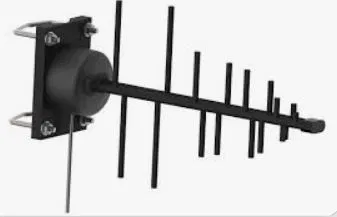
9. Airborne Antenna: These antennas are used in various airborne platforms as radio navigation and communication systems. Airborne antennas are designed for use in difficult surroundings for years of optimum efficiency and trouble-free operation. The systems are used in an array of custom frequency bands, military, scientific, and standard commercial bands. These antennas are used as part of the data link system for communications on aircraft.

MICROWAVE LINK INSTALLATION, ALIGNMENT AND TESTING
One of our services involves the installation of Microwave Antenna or Microwave Links and GSM Radios. Microwave links are widely used for point-to-point communications because their small wavelength allows conveniently-sized antennas to direct them in narrow beams, which can be pointed directly at the receiving antenna. This allows nearby microwave equipment to use the same frequencies without interfering with each other, as lower-frequency radio waves do.
Microwave Link Installation
Microwave link installation is performed by X-PLUS TELECOMS qualified and certified crews. Crews can be scaled to meet the build-out market demand and project schedule. All resources within a crew adhere to all local safety laws and carry safety certifications. Microwave link installation includes:
- Rooftop, tower, or monopole locations through the use of riggers (crane, bucket extra)
- Installation of dish antenna on existing antenna mast
- Installation of ODUs and IDUs as per link design
- Running, labeling, and securing of required cables (Cat5e, IF, fiber, power)
- Termination of connectors at ODU and IDU ends, with assurance of connectivity, strain relief, taped/waterproofed/tie wrapped.
- Installation of grounding cable
- Installation of DC power cable from customer-provided power source and breakers
- Validation of correct power and grounding of the system
- Validation of all of the cables through cable testers
- Confirmation of installation quality through established punch-list
- Detailed photographs of the installation
- Comprehensive MOP – outlining installation procedures and configuration details
Link Alignment and Testing
After microwave link installation, X-PLUS TELECOMS & TOWERS certified resources perform microwave link alignment and testing.
The link alignment and testing service includes:
- Precise alignment of antennae at both ends of the link
- Any final radio configurations as required
- Validation of traffic continuity of the link at the link-designed throughput speeds
- Measurement of latency and throughput values using standard RFC tests
- 1 (one) hour Bit Error Rate test to confirm error-free traffic for the link between link demark endpoints (RJ45 connector terminating at the local switch or BTS)
- Completion of Acceptance Test Plan
Close Out Package
With the completion of each microwave link installation, X-PLUS TELECOMS & TOWERS provides a complete Closeout Package (COP) which includes as a minimum:
- Marked up (customer-supplied) construction documentation showing “as-built” for each site
- Microwave test results as output from link testing (RFC, BER)
- Radio configuration and diagnostic files, including RF actuals vs. RF design parameters
- Photos of complete installation – cabinet, lines, tower, etc.
- Site coordinate information
- Serial numbers of each product deployed
Microwave Link Decommissioning
Microwave link decommissioning is performed by X-PLUS TELECOMS & TOWERS qualified and certified crews. Crews with remove existing legacy equipment and dispose by a customer or in an environmentally conscience manner.
Fully resourced and trained teams of Engineers, Technicians, and Riggers Install and Commission all major OEM suppliers’ Radio and High Capacity Optical Transmission equipment (SDH/PDH). We also provide documented frequency and tributary management records as part of the acceptance procedures. Transmission planning, including installation of very small aperture terminals (VSAT), is offered as part of a full range of transmission services. Our radio and transmission planning service includes ➢ Optic fiber route planning➢ PDH and SDH transmission link planning budget


